Transforming Control flow to Data flow
This is in continuation to my earlier introductory post on Spatial Computing project I have been working on.
I spent my last few days transforming the traditional control flow of the programs into a data flow graph having producer consumer relationship between the instructions. As mentioned in my previous post, this data flow when executed on a data flow architecture that we have been trying to build for ASICs and then later for general purpose computers would be using the highest level of parallelism available because of the producer-consumer relationship between the instructions.
There are some programming constructs which are hard to transform from sequential to data flow. Loops, pointers, pointers to functions are some of them that needs extensive care. This post is more about the results from my project. I will be showing the transformation for single loop just for the sake of simplicity :
Sample Code
 int sum_single_loop (int a){

 int sum = 0;
 for (int i = 0; i < a; i++)
     sum = sum + i;

 }
I am making use of LLVM IR format, so I convert all the code in imperative
languages which are having their LLVM front-end avilable, to LLVM IR format. This would
help me deal with a lot of languages. We have clang that can emit LLVM IR for
any given C code. So I use clang to emit LLVM and then run the LLVM passes I
have written for transforming this control flow graph to data flow graph. The
passes use CFG (Control Flow Graph) as a reference, they take the necessary
information from the CFG and create a DFG out of it while keeping the
correctness of the program intact. After all, that’s the most important thing we
don’t want to let happen before performance.
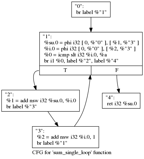
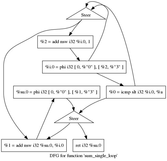
Here are the corresponding CFG (generated using clang and opt - LLVM) and transformed DFG below that (transformed using LLVM passes) for above code.

Above graph consists of 5 basic blocks with their labels on their top.
You should be able to understand all the LLVM instructions if you are
familiar with
assembly level programming except the PHI instructions which takes a set of
array (two in this case) and assigns the first argument of these arrays, to the
variable on left side. Since there are two such values in this case, it assigns
the value as soon as it receives any one of it. The second argument of these
arrays tells the name of the basic block from where this first argument will
come from. The constant 0 in PHI instruction is there to trigger the
program from outside.

Here is the transformed DFG using CFG above. You can see I have used Steer
nodes to eliminate the branch instructions. The steer nodes as the name suggests
sends the value coming from its top to its left if the select pin (coming in to its
right) is true and to its right if its false. In other words it works as a
demultiplexer. You can also see that some of the steer nodes only have one
output value to its bottom left but no value on its bottom right. It means that
the value on the right is not needed and hence is sinked.
Also, note that su.0 and i.0 instructions in above DFG are still triggers in
executing this data flow graph as explained above due to PHI instruction.
The LLVM passes I have written are in a very dirty state as of now. I still have to deal with Load/Store instructions so that I can deal with pointers in programming languages as they and the operations using them on memory are something very fundamental if I have to cover up any programming language fully. I also need to add some mechanism of waves that we have theortically solved to keep the data flow cycles in sync with each other to maintain the program correctness.
blog comments powered by Disqus